Introduction
In the intricate world of fluid dynamics and industrial machinery, few components boast the ubiquity, reliability, and historical significance of the gear pump. As a cornerstone of the positive displacement (PD) pump family, the gear pump has served as the circulatory heart of hydraulic systems, chemical processing plants, and lubrication circuits for over a century. Its fundamental premise—using the mechanical meshing of gears to trap and transport fluid volumes—is elegantly simple, yet the engineering required to optimize this mechanism for modern high-pressure, high-viscosity applications is profoundly complex.
For the B2B buyer, the procurement of a gear pump is not merely a purchase of hardware; it is an investment in system uptime and efficiency. A mismatch in pump selection can lead to catastrophic system failures, ranging from cavitation-induced erosion to seal blowouts and production halts. For the engineer, the gear pump represents a critical variable in the system design equation, where flow rates must be precise, pressures must be stable, and mechanical efficiency must be maximized against the constraints of fluid viscosity and temperature.
This comprehensive report serves as an exhaustive technical resource. It moves beyond superficial definitions to explore the deep physics of gear pump operation, the metallurgical considerations of material selection, and the critical distinctions between the two dominant architectures: the External Gear Pump and the Internal Gear Pump. By synthesizing industry-standard data, theoretical fluid mechanics, and practical field experience, this guide aims to empower stakeholders to make data-driven decisions that align with the rigorous demands of modern industrial applications.
The Role of Gear Pumps in the Hydraulic Ecosystem
The hydraulic ecosystem is vast, encompassing everything from the micro-hydraulics of medical devices to the massive actuation systems of offshore drilling rigs. Within this spectrum, pumps are the primary energy converters, transforming mechanical torque from a prime mover (electric motor or internal combustion engine) into hydraulic energy (flow and pressure).
While centrifugal pumps dominate the world of water and low-viscosity fluid transfer due to their kinetic energy principles, they falter when faced with high pressures or viscous fluids. Here, the gear pump asserts its dominance. As a positive displacement device, it delivers a fixed volume of fluid for every rotation of the shaft, regardless of the discharge pressure (theoretically). This characteristic makes it indispensable for:
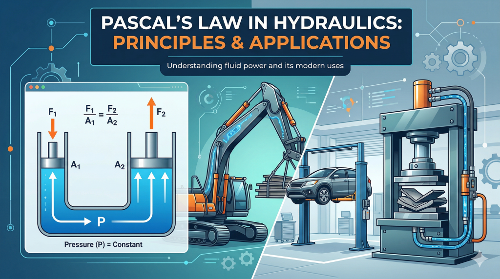
Hydraulic Power: Providing the force to lift excavator arms, clamp injection molds, and steer ships.
Fluid Transfer: Moving heavy fuel oils, resins, and polymers that would stall a centrifugal pump.
Lubrication: Ensuring a constant film of oil protects critical bearings in turbines and engines.
Understanding the gear pump requires a deep dive into its anatomy, its variations, and the fluid dynamics that govern its life cycle.
Section 1: How Does a Gear Pump Work?
To select, operate, or troubleshoot a gear pump effectively, one must first grasp the fundamental physics governing its operation. Unlike rotodynamic pumps (centrifugal, axial) that impart velocity to a fluid which is then converted to pressure, gear pumps operate on the principle of volume displacement.
1.1 The Fundamental Cycle of Operation
The operation of any gear pump, regardless of its specific architecture, follows a continuous, three-stage cycle: Suction (Fill), Transfer (Displacement), and Discharge (Squeeze).
Phase 1: Suction (The Fill)
The process begins at the pump inlet. As the gears rotate, the teeth on the intake side unmesh (separate). This physical separation expands the volume of the cavity between the gear teeth and the pump housing. According to Boyle’s Law, as volume increases, pressure decreases. This expansion creates a localized vacuum (or, more accurately, a region of pressure lower than the atmospheric or tank pressure).
Fluid from the reservoir is pushed by atmospheric pressure (or a charge pump) into this low-pressure zone, filling the cavities between the gear teeth. It is critical to note that the pump does not “suck” fluid; the external atmospheric pressure pushes the fluid into the void created by the unmeshing gears. This distinction highlights the importance of inlet conditions—if the supply pressure is insufficient to overcome friction losses in the inlet line, the fluid cannot fill the cavity fast enough, leading to cavitation.
Phase 2: Transfer (The Displacement)
Once the fluid is trapped in the gear tooth cavities, it is sealed between the gear tips and the pump housing (the stator). As the gears continue to rotate, these trapped volumes of fluid are transported around the periphery of the pump—not through the center.
In an external gear pump, the fluid splits into two streams, traveling along the top and bottom arcs of the casing. In an internal gear pump, the fluid travels in the spaces between the rotor and idler, separated by a crescent seal. During this phase, the fluid is essentially static relative to the gear teeth; it is simply being carried from the low-pressure side to the high-pressure side.
Phase 3: Discharge (The Squeeze)
As the gears reach the outlet side, the teeth begin to mesh (interlock) once again. The volume available for the fluid is rapidly reduced as the tooth of one gear enters the slot of the mating gear. Since hydraulic fluid is virtually incompressible, it is forcibly ejected from the cavity. The close tolerances between the gears and the casing prevent the fluid from leaking back to the inlet, forcing it out through the discharge port and into the system.
1.2 Gear Geometries and Tribology
The geometry of the gears dictates the pump’s noise level, pressure capability, and flow smoothness.
Spur Gears
The spur gear is the most common geometry in external gear pumps. The teeth are cut straight and parallel to the axis of rotation.
Mechanism: The entire width of the tooth engages simultaneously across the face.
Implication: This results in excellent volumetric efficiency and high pressure capability due to uniform sealing. However, the instantaneous engagement and disengagement create trapped volumes that can cause pressure spikes, leading to significant noise and flow pulsation (ripple).
Helical Gears
Helical gears feature teeth cut at an angle (helix angle) to the shaft axis.
Mechanism: Engagement is gradual; the leading edge of the tooth enters the mesh before the trailing edge.
Implication: This gradual engagement significantly reduces hydraulic noise and vibration, resulting in a smoother flow. However, the angled teeth generate axial thrust loads, pushing the gears against the housing thrust plates. This requires robust thrust bearings and limits the maximum pressure compared to spur gears.
Herringbone (Double Helical) Gears
Herringbone gears consist of two helical profiles mirrored in a “V” shape.
Mechanism: The opposing helix angles cancel out the axial thrust forces while maintaining the smooth engagement of helical gears.
Implication: These are used in high-flow, heavy-duty applications where pulsation must be minimized, and bearing life maximized. They are structurally complex and more expensive to manufacture.
1.3 Volumetric Efficiency and Internal Slippage
No gear pump is 100% efficient. The theoretical flow rate ($Q_t$) is calculated based on the displacement volume per revolution and the rotational speed. However, the actual flow rate ($Q_a$) is always lower due to internal slippage (or “blow-by”).
\[ \eta_v = \frac{Q_a}{Q_t} \times 100 \]
Tip Clearance: The gap between the gear tip and the housing bore.
Side Clearance: The gap between the gear face and the side plates (bushings).
Mesh Clearance: The sealing contact between the meshing teeth.
Fluid slips from the high-pressure discharge side back to the low-pressure suction side. This slip is exacerbated by:
High Discharge Pressure: Drives more fluid through the gaps.
Low Fluid Viscosity: Thinner fluids flow more easily through tight clearances.
Pump Wear: As clearances open up over time, efficiency drops drastically.
Section 2: Internal Gear Pump vs. External Gear Pump
The distinction between internal and external gear pump architectures is the single most critical decision in the specification process. While they share the fundamental “fill, transfer, squeeze” principle, their mechanical implementations create vastly different performance envelopes regarding pressure, viscosity, and durability.
2.1 External Gear Pumps: The Hydraulic Powerhouse
The external gear pump is the industry standard for high-pressure hydraulic applications. Its design prioritizes structural rigidity and speed, allowing it to generate the immense forces required by modern machinery.
Mechanical Architecture
An external gear pump consists of two identical gears—a driving gear (connected to the motor shaft) and a driven gear (idler)—positioned side-by-side in a figure-eight housing.
Shaft Support: Critical to its high-pressure capability is the support method. Both gears are supported by shafts with bearings on both sides of the gear face. This “straddle” mounting minimizes shaft deflection under load, preventing the gears from grinding against the housing walls.
Bearings: Typically utilizes four bearings (bushings or needle roller bearings). These bearings are lubricated by the pumped fluid, which imposes a limitation: the fluid must have sufficient lubricity and be free of large particulates.
Performance Characteristics
High Pressure: Due to the rigid shaft support and tight tolerances, external gear pumps can routinely sustain continuous pressures of 3,000–3,500 psi (210–250 bar). Specialized “high-pressure” variants utilizing cast iron bodies and pressure-balanced wear plates can reach 4,000+ psi (280 bar).
Speed & Efficiency: They are designed for high-speed operation (often 1,500–3,000 RPM). At these speeds, and with medium-viscosity hydraulic oil, they achieve high volumetric efficiencies (often >90%).
Noise: They are inherently louder than internal types. The high speed, combined with the “trapped volume” phenomenon in spur gears, creates a distinct high-frequency whine.
Limitations
Viscosity Limits: While excellent for hydraulic oils (10–100 cSt), they struggle with extremely high viscosities. The high operational speed does not allow sufficient time for thick fluids to fill the cavities, leading to cavitation. Generally, they are limited to fluids under 2,000–5,000 cSt unless run at significantly reduced speeds.
Shear: The high-speed meshing action creates high fluid shear. This is acceptable for oil but destructive for shear-sensitive fluids like latex, flocculants, or food products.
2.2 Internal Gear Pumps: The Viscosity & Precision Specialist
The internal gear pump operates on a “gear-within-a-gear” principle. It is the preferred technology for fluid transfer, chemical dosing, and handling difficult, viscous liquids.
Mechanical Architecture
This pump features a larger external rotor gear (with inward-facing teeth) driving a smaller internal idler gear. A stationary crescent-shaped seal is machined into the head or casing to separate the suction and discharge zones.
Cantilevered Design: Unlike the external type, the idler gear is typically supported by a pin on only one side (cantilevered). This design simplifies the flow path but creates a structural weak point that limits maximum pressure capabilities.
Longer Flow Path: The engagement of the gears is much more gradual, and the fluid travels a longer arc. This results in a gentle pumping action with minimal pulsation.
Performance Characteristics
Viscosity Handling: This is the internal gear pump’s superpower. It can handle fluids from 1 cP (solvents) up to 1,000,000+ cP (asphalt, peanut butter, adhesives). The large, open cavities and typically lower rotational speeds allow thick fluids to enter the pump without cavitating.
Suction Lift (NPSHr): Internal gear pumps have excellent self-priming capabilities and low Net Positive Suction Head required (NPSHr). This makes them ideal for stripping tanks or lifting fluid from underground reservoirs.
Shear Sensitivity: The slow, rolling engagement of the teeth minimizes turbulence and shear. This is critical for pumping polymers, paints, and food products where texture or molecular structure must be preserved.
Quiet Operation: They are significantly quieter than external gear pumps due to the lower speeds and smoother mesh geometry, making them suitable for indoor plant environments.
Limitations
Pressure Limits: The cantilevered support of the idler pin limits the pressure handling. Standard models are often rated for 100–250 psi (7–17 bar). While high-performance “hydraulic” internal gear pumps (like the Truninger or Eckerle designs) can reach 3,000 psi, the vast majority of industrial transfer pumps are medium-pressure devices.
Solids Tolerance: Like all gear pumps, they generally dislike solids. However, because they have fewer bearings in the fluid and larger cavities, they are slightly more forgiving of soft, suspended solids than external types.
2.3 Comprehensive Comparison Table
The following table synthesizes data from multiple industry sources to provide a direct comparison for selection purposes
| Feature | External Gear Pump | Internal Gear Pump |
| Primary Design Philosophy | Speed, Pressure, Power Density | Viscosity, Suction, Smooth Flow |
| Max Pressure (Standard) | 3,000 – 3,500 psi (210-240 bar) | 200 – 300 psi (14-20 bar) |
| Max Pressure (High Perf.) | 4,000+ psi (280 bar) | 3,000 – 4,000 psi (Specialized Hydraulic designs) |
| Viscosity Range | 10 to ~5,000 cSt (Best for Oils) | 1 to 1,000,000+ cSt (Best for Resins/Food) |
| Rotational Speed | High (1,200 – 3,500 RPM) | Low to Medium (50 – 1,800 RPM) |
| Suction Lift / Self-Priming | Moderate | Excellent (Superior vacuum generation) |
| Flow Characteristic | Pulsating (High Ripple in Spur gears) | Smooth, Pulse-free, Constant Velocity |
| Noise Level | High (Whine) | Low (Quiet) |
| Shear Impact on Fluid | High (High shear) | Low (Gentle handling) |
| Maintenance Cost | Low (Often “Throw-away” item in small sizes) | Moderate/High (Rebuildable, more parts) |
| Bearing Support | Dual-sided (Straddle) – Rigid | Single-sided (Cantilever) – Overhung load risk |
Section 3: Key Applications
The bifurcation of gear pump technology into Internal and External designs allows this pump class to serve a staggering array of industries. From the high-pressure violence of a rock crusher to the delicate flow of a chocolate coating line, gear pumps are omnipresent.
3.1 Hydraulic Power Units (HPUs) and Mobile Equipment
Dominant Type: External Gear Pump.
Context: Excavators, forklifts, log splitters, and industrial presses all utilize hydraulic fluid to transmit power.
Why External? The primary requirement here is pressure density. An external gear pump is compact, cheap, and can withstand the pressure spikes associated with actuating hydraulic cylinders. The fluid is clean hydraulic oil (typically ISO VG 32, 46, or 68), which is the ideal medium for external gear pumps.
Deep Dive: In mobile hydraulics, these pumps are often mounted in tandem (multiple pumps on one shaft) to supply different circuits (e.g., one for steering, one for the boom) from a single engine drive. Their volumetric efficiency at 3,000 psi ensures that engine power is effectively converted to lifting force.
3.2 Petrochemical, Oil & Gas (API 676 Applications)
Dominant Type: Internal Gear Pump (and Screw Pumps).
Context: Transferring crude oil, bitumen, asphalt, tar, and refined fuels at refineries and terminals.
Why Internal? These fluids vary wildly in viscosity. Cold bitumen is essentially a solid; hot bitumen is a thin liquid. Internal gear pumps are robust enough to handle the high torque of cold starts. Furthermore, they can be fitted with heating jackets—chambers cast into the pump housing that circulate steam or hot oil to keep the product fluid.
Regulatory Standard: API 676 is the governing standard for rotary positive displacement pumps in this sector. It dictates strict requirements for casing wall thickness, flange loads, and seal chambers to ensure safety in hazardous environments. Internal gear pumps are frequently manufactured to meet these rigorous specifications.
3.3 Chemical Processing and Polymer Production
Dominant Type: Internal Gear Pump (Precision Metering).
Context: Dosing catalysts, pumping resins, isocyanates, and polyols for polyurethane foam production.
Why Internal?
Metering Accuracy: Because the flow is directly proportional to speed and slippage is predictable, these pumps can act as metering devices. When paired with a closed-loop VFD, they achieve accuracy better than +/- 1%.
Viscosity Handling: Polymers are often extremely viscous.
Shear Sensitivity: Many long-chain polymers degrade if sheared. The gentle action of the internal gear pump preserves the chemical integrity of the product.
3.4 Food and Beverage Production
Dominant Type: Internal Gear Pump (Sanitary Design).
Context: Moving chocolate mass, corn syrup, peanut butter, glucose, and vegetable oils.
Why Internal?
Sanitary Standards: These pumps can be constructed from 316L Stainless Steel with polished internals to prevent bacterial growth. They are designed for Clean-in-Place (CIP) or Strip-Clean-in-Place (SCIP) protocols.
Texture Preservation: Chocolate is shear-sensitive; excessive agitation changes its tempering and texture. Internal gear pumps move it gently.
Solid Tolerance: Some internal gear pump designs (loose clearance) can handle fluids with soft solids, like chunky peanut butter or fruit pulps, without crushing them.
3.5 Automotive Lubrication
Dominant Type: Gerotor (Internal Gear Variant) and External Gear.
Context: The oil pump inside every internal combustion engine.
Why? Reliability is non-negotiable. If the oil pump fails, the engine is destroyed in seconds. Gerotor pumps are compact, have few moving parts, and mount directly around the crankshaft, providing a fail-safe lubrication flow proportional to engine speed.
Section 4: Selection Guide
Selecting a gear pump is an engineering balancing act. It requires a holistic view of the fluid’s properties, the system’s demands, and the environmental conditions.
4.1 Viscosity: The Governing Variable
Viscosity is the measure of a fluid’s resistance to flow. In gear pump selection, it dictates speed, power, and pump type.
Low Viscosity (< 20 cSt):
Risk: High slippage. The fluid leaks back through clearances, reducing flow and pressure capability.
Action: Select a pump with tight internal clearances. Avoid running at low speeds, as slip becomes a larger percentage of total flow. External gear pumps are often preferred here due to tighter manufacturing tolerances.
High Viscosity (> 2,000 cSt):
Risk: Cavitation. The fluid is too thick to fill the tooth cavities at standard motor speeds.
Action: Reduce Pump Speed. As viscosity increases, RPM must decrease. For example, pumping 10,000 cSt resin might require running at only 200 RPM.
Action: Select Internal Gear Pumps with “Loose” or “Extra Clearance” rotors. Use larger suction port sizes to reduce friction losses.
Table: Viscosity vs. Recommended Speed (General Guideline
| Fluid Viscosity (cSt/SSU) | Typical Pump Speed (RPM) | Pump Preference |
| 1 – 100 (Water, Solvents) | 1,450 – 3,450 | Internal (Carbon bearings) or External |
| 100 – 1,000 (SAE 30 Oil) | 1,150 – 1,750 | External or Internal |
| 1,000 – 5,000 (Gear Oil) | 750 – 1,150 | Internal |
| 5,000 – 25,000 (Resins) | 200 – 500 | Internal |
| 25,000+ (Pastes, Asphalt) | < 200 | Internal (Heavy Duty) |
4.2 Pressure Requirements
System Head: Calculate the Total Dynamic Head (TDH) in psi or bar.
If Pressure > 500 psi (35 bar): You are almost certainly in External Gear Pump territory.
If Pressure < 200 psi (14 bar): An Internal Gear Pump offers smoother flow and better suction.
Relief Protection: CRITICAL: Gear pumps are positive displacement. If the discharge line is blocked, pressure will rise until something breaks (shaft shears, pipe bursts, motor burns out). A Pressure Relief Valve (PRV) is mandatory. Most pumps offer an integrated relief valve, but an external return-to-tank valve is safer for thermal management.
4.3 Material Selection and Corrosion
The pump materials must be chemically compatible with the fluid.
Cast Iron: The standard for oils, fuels, and non-corrosive hydrocarbons. Robust, cheap, and has good self-lubricating properties.
Stainless Steel (316): Required for corrosive acids, food products, and water-based fluids that would rust iron. Warning: Stainless steel has poor galling resistance. 316 SS gears running against a 316 SS case will seize. Manufacturers use specialized bushings (Carbon Graphite, PEEK) or hardened coatings (Armoloy) to prevent this.
Bronze: Used for seawater applications (marine pumps) to prevent galvanic corrosion. Also used in explosive environments as it is non-sparking.
Hardened Steel: For abrasive fluids (inks, paints with oxides). Standard gears will wear in hours. Nitrided or Tungsten Carbide coated internals are required.
4.4 Temperature Considerations
Clearance Reduction: Metal expands when hot. If a pump built for 20°C is run at 200°C, the gears will expand and seize in the housing.
Action: Specify the operating temperature to the manufacturer so they can machine “hot clearance” into the pump.
Thermal Shock: Rapid temperature changes (e.g., hitting a cold pump with 200°C oil) can crack cast iron casings. Preheat procedures are required.
Section 5: Common Troubleshooting & Maintenance
Even the most robust gear pumps are susceptible to failure if operational conditions drift outside their design envelope. Effective maintenance relies on understanding the “symptoms” of pump distress.
5.1 Cavitation: The Silent Killer
Cavitation is the formation and collapse of vapor bubbles within the liquid.
Mechanism: If suction pressure drops below the fluid’s Vapor Pressure, the fluid boils at ambient temperature. The bubbles form in the inlet and collapse violently on the discharge side, blasting material off the gears and casing.
Symptoms: Distinctive noise sounding like “gravel” or “marbles” in the pump. Excessive vibration. Pitting damage on the gear teeth faces.
Root Causes: Clogged suction strainer, inlet pipe too small (high friction), fluid too viscous (cold start), or pump running too fast.
Solution: Increase NPSHa (raise tank level, pressurize tank). Reduce speed. Heat the fluid to reduce viscosity. Clean filters.
5.2 Aeration (Air Entrainment)
Often confused with cavitation, aeration is the presence of air bubbles in the fluid before it enters the pump.
Symptoms: Whining or howling noise. Foamy fluid in the reservoir. Jerky actuator movement.
Root Causes: Loose suction line fittings (sucking air), low reservoir level (vortexing), or a failed shaft seal allowing air ingress.
Solution: Tighten all suction-side connections. Check tank levels.
5.3 Internal Wear and Efficiency Loss
Symptoms: The pump runs, but flow rate decreases as pressure increases. The pump struggles to build pressure. The case becomes hot.
Root Causes: Abrasive wear has opened up the tip and side clearances. Fluid is slipping back to the inlet.
Solution: Check filtration. Gear pumps require clean fluid (typically 10-25 micron filtration). Replace worn gears, shafts, and wear plates. If the housing bore is scored, the pump (or housing) must be replaced.
5.4 Seal Failure
Symptoms: Visible leakage at the shaft.
Root Causes: Chemical incompatibility (O-ring swelling), misalignment of the motor coupling (causing shaft deflection), or over-pressurization of the seal chamber.
Solution: Verify elastomer compatibility (Viton vs. Buna vs. PTFE). Check coupling alignment with a laser or dial indicator. Ensure the seal drain line is not blocked.
Maintenance Checklis
| Interval | Action Item |
| Daily | Listen: Check for cavitation/aeration noise. Visual: Check for shaft seal leaks. Touch: Monitor motor and pump temperature. |
| Weekly | Check Fluid: Verify reservoir level and condition (foam/color). Filters: Inspect differential pressure indicators on suction strainers. |
| Monthly | Alignment: Check coupling alignment and insert wear. Relief Valve: Verify pressure setting hasn’t drifted. |
| Annually | Oil Analysis: Check for metal particulate spikes (indicates internal wear). Performance Test: Measure flow at rated pressure; if <80% of new, rebuild/replace. |
FAQ Section
Q1: Can gear pumps run dry? A: Generally, no. Gear pumps rely on the pumped fluid to lubricate the internal bearings (bushings) and seal the gaps between the gears. Running dry leads to rapid heat buildup, friction, and seizure—often within minutes. If dry running is a possibility (e.g., tank stripping), you must use specialized materials like Carbon Graphite bushings and Silicon Carbide seals, but even these have time limits.
Q2: What is the difference between a “Gerotor” and a standard Internal Gear Pump? A: A Gerotor is a specialized type of internal gear pump. It lacks the “crescent” seal found in standard designs. Instead, the inner and outer gear geometries (trochoidal) are designed so that the rotor tips maintain continuous contact to seal the fluid zones. Gerotors are extremely compact and inexpensive, making them standard for automotive oil pumps, but they generally have lower pressure and viscosity capabilities than crescent-type pumps.
Q3: Why is my external gear pump so loud? A: External gear pumps, especially those with spur gears, trap small volumes of fluid between the meshing teeth. As these teeth mesh, this trapped fluid is compressed, causing a pressure spike and noise (ripple). High rotational speeds (3,000 RPM) exacerbate this. Switching to helical gears or an internal gear pump design will significantly reduce noise.
Q4: How does viscosity affect motor sizing? A: Viscosity creates drag. Pumping honey requires significantly more torque (and thus horsepower) than pumping water. Engineers must calculate the Viscous Horsepower (VHP) in addition to the Hydraulic Horsepower. Failing to account for this will cause the electric motor to trip its overload breaker or burn out.
Q5: Can gear pumps handle abrasives? A: Not well. The tight tolerances (often <0.002″) that make them efficient also make them vulnerable. Abrasive particles get trapped in these gaps and act like sandpaper, destroying the pump. For mild abrasives (inks, paints), you can use internal gear pumps with hardened materials (Tungsten Carbide bushings, Nitrided gears) and run them at very low speeds to minimize erosion.
Conclusion
The gear pump remains a marvel of industrial utility. Its ability to provide consistent, reliable flow across a vast spectrum of viscosities and pressures ensures its place in the engineer’s toolkit for the foreseeable future.
For the B2B buyer, the key to successful procurement lies in understanding the specific demands of the application. The External Gear Pump is the champion of hydraulic power—compact, forceful, and economical. The Internal Gear Pump is the master of fluid transfer—versatile, gentle, and capable of moving the most difficult liquids on earth.
By carefully evaluating the critical parameters—viscosity, pressure, temperature, and chemical compatibility—and selecting the appropriate pump architecture and materials, organizations can achieve systems that are not only efficient but enduring. Whether powering the arm of an excavator or precisely dosing the ingredients of a pharmaceutical, the gear pump, when chosen correctly, is a component you can install and essentially forget, trusting it to perform its cycle of “Fill, Transfer, Squeeze” billions of times over.