
In the complex landscape of positive displacement fluid dynamics, the selection of the correct pumping architecture is the single most critical determinant of system efficiency, longevity, and operational cost. Gear pumps, a cornerstone of industrial hydraulics and chemical processing, are categorized into two primary engineering topologies: the Internal Gear Pump and the External Gear Pump. While both operate on the fundamental principle of rotary displacement—using the meshing of gears to trap and transport fluid volumes—their structural executions result in drastically divergent performance envelopes.
This exhaustive technical report provides a definitive analysis for engineers, procurement officers, and maintenance managers. Our research indicates that External Gear Pumps are the superior choice for high-pressure hydraulic applications (up to 3,000+ PSI), offering compact power density and cost-effectiveness for low-viscosity fluids. Conversely, Internal Gear Pumps dominate the spectrum of high-viscosity and shear-sensitive fluid handling (up to 1,000,000 cP), providing superior suction lift capabilities, reduced pulsation, and quieter operation. By examining the tribological interactions, fluid dynamic behaviors, and acoustic characteristics of each design, this guide aims to eliminate selection errors and optimize industrial fluid handling strategies.
1. Introduction to Rotary Positive Displacement Technology
To fully appreciate the distinctions between internal and external gear pumps, it is essential to first ground the discussion in the physics of Positive Displacement (PD) pumping. Unlike kinetic pumps (such as centrifugal pumps) which impart velocity energy to a fluid that is subsequently converted into pressure energy, positive displacement pumps operate by expanding a cavity on the suction side and collapsing it on the discharge side.
1.1 The Mechanics of Volume Trapping
Both internal and external gear pumps function by trapping a fixed amount of fluid—a “finite volume”—between the teeth of rotating gears. This process creates a mechanical seal between the pump inlet and outlet. As the gears rotate, this trapped volume is physically pushed from the low-pressure suction zone to the high-pressure discharge zone.
The fundamental equation governing the theoretical flow rate ($Q_{th}$) of any gear pump is:
Where:
-
$Q_{th}$ is the theoretical flow rate.
-
$V_d$ is the displacement volume per revolution.
-
$N$ is the rotational speed (RPM).
However, the actual performance of these pumps in the field is dictated by volumetric efficiency ($\eta_v$), which introduces the concept of slip. Slip is the leakage of fluid from the high-pressure discharge side back to the low-pressure suction side through the internal clearances of the pump.
The architectural differences between internal and external gear pumps—specifically how they manage these clearances, support the gear shafts, and configure the flow path—determine their respective slip characteristics, pressure handling capabilities, and suitability for different fluid viscosities.
1.2 The Criticality of Viscosity
Viscosity is the resistance of a fluid to flow and shear. It is the defining variable in gear pump selection.
-
Low Viscosity Fluids (e.g., Solvents, Diesel, Water): These fluids flow easily through tight clearances, increasing slip. To pump them efficiently, tighter manufacturing tolerances are required. External gear pumps are often preferred here due to their ability to run at high speeds, which helps “outrun” the slip.
- High Viscosity Fluids (e.g., Resins, Asphalt, Molasses): These fluids resist flow, creating significant mechanical drag (viscous friction) on the pump components. However, they also act as a sealant, reducing slip. Internal gear pumps are the standard here due to their robust tooth profiles and lower operating speeds, which prevent cavitation and reduce shear stress.
2. Anatomy and Engineering of the External Gear Pump
The External Gear Pump is the workhorse of the mobile hydraulic industry. Its design prioritizes structural rigidity and pressure capability over viscosity flexibility.
2.1 Structural Configuration
An external gear pump consists of two identical gears—a driving gear (connected to the motor shaft) and a driven gear (idler)—that are positioned side-by-side. The gears mesh externally, meaning their pitch circles are tangent to each other.
2.1.1 Shaft Support Systems
The defining structural feature of the external gear pump is its bearing arrangement. Because the gears are mounted on separate, parallel shafts, each shaft is supported by bearings on both sides of the gear face. This “simply supported beam” configuration is structurally superior to cantilevered designs. It minimizes shaft deflection under high hydraulic loads, allowing the pump to maintain tight internal clearances even at pressures exceeding 3,000 PSI (200 Bar).
2.1.2 Gear Profiles
The geometry of the gear teeth dictates the pump’s acoustic and flow characteristics:
-
Spur Gears: Straight-cut teeth parallel to the axis. These are the most common and cost-effective. However, they suffer from high noise levels because the entire length of the tooth engages simultaneously, creating a significant pressure ripple.
-
Helical Gears: Teeth are cut at an angle. This allows for progressive engagement, significantly reducing noise and vibration. The trade-off is the generation of axial thrust loads, which requires more robust thrust bearings and creates internal friction.
-
Herringbone (Double Helical) Gears: These gears feature a V-shaped tooth profile. They cancel out the axial thrust inherent in helical gears while maintaining the quiet operation. They are typically used in larger, high-flow external gear pumps but prevent the pump from being bi-rotational due to fluid trapping characteristics in the apex of the “V”.
2.2 Operational Cycle
The pumping cycle of an external gear pump involves three distinct phases :
-
Suction Phase: As the gears come out of mesh at the pump inlet, the volume of the cavities expands. This expansion creates a partial vacuum (pressure differential), causing atmospheric pressure to force fluid from the reservoir into the pump.
-
Transfer Phase: Fluid is trapped in the pockets formed between the gear teeth and the pump housing (casing). The fluid travels around the periphery of the gears. It is crucial to note that fluid does not pass between the gears; the meshing point acts as a moving seal.
-
Discharge Phase: As the gears rotate back into mesh at the outlet, the volume of the cavities is reduced. The meshing teeth mechanically displace the fluid, forcing it out of the discharge port against the system pressure.
2.3 Distinct Advantages
-
High Pressure Capability: The rigid shaft support allows external gear pumps to withstand massive differential pressures, making them the standard for hydraulic power units (HPUs) in construction machinery.
-
Compact Footprint: The design is inherently dense, offering a high power-to-weight ratio.
-
Cost-Effectiveness: Due to the symmetrical design and ease of manufacturing (often using sintered metal gears), external gear pumps typically have a lower initial purchase price compared to internal designs.
2.4 Inherent Limitations
- Shear & Agitation: The high rotational speeds (often 1,750 or 3,450 RPM) and tight clearances generate high shear rates. This makes them unsuitable for shear-sensitive fluids like latex or long-chain polymers.
- Solids Intolerance: With clearances as tight as 0.0005 inches, external gear pumps have virtually no tolerance for suspended solids. Particles can become trapped between the gear tip and housing, causing “plowing” or catastrophic seizure.
- Noise: Standard external gear pumps are notoriously noisy due to the trapping of incompressible fluid in the mesh (backlash) area, creating pressure spikes known as fluidborne noise.
3. Anatomy and Engineering of the Internal Gear Pump
The Internal Gear Pump, often referred to as the “gear-within-a-gear” principle, is the versatile problem-solver of the industrial world. It excels where external gear pumps fail: moving thick, fragile, or difficult fluids.
3.1 Structural Configuration
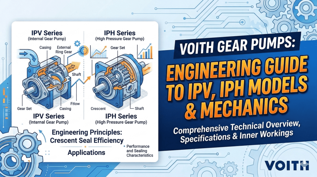
An internal gear pump features a larger outer gear (the rotor) with teeth on the inside circumference, and a smaller inner gear (the idler) with teeth on the outside. The idler is positioned eccentrically (off-center) inside the rotor.
3.1.1 The Crescent Seal
In the most common internal gear design, a stationary, crescent-shaped partition is machined into the pump head. This crescent fills the void created by the off-center placement of the idler. It acts as a seal, separating the suction port from the discharge port. The tips of both the rotor and idler gears ride along this crescent, creating a long sealing path that minimizes slip.
3.1.2 The Gerotor Variant
A specialized subset of the internal gear family is the Gerotor (Generated Rotor). In this design, the inner gear has one less tooth than the outer gear, and there is no crescent. The sealing is achieved by the sliding contact of the gear tips themselves. Gerotors are extremely compact and are ubiquitous in automotive oil pumps, but they generally lack the pressure capabilities of crescent-type pumps.
3.2 Operational Cycle
-
Suction Phase: As the rotor drives the idler, the gears un-mesh at the inlet port. This creates an expanding volume that draws fluid in. Because the gears un-mesh over a longer degree of rotation compared to external pumps, the suction is gentler and more effective.
-
Transfer Phase: Fluid enters the cavities between the gear teeth. Unlike the external pump where fluid moves around the outside, here the fluid moves through the pump in the spaces between the gear teeth and the crescent.
-
Discharge Phase: The rotor and idler mesh again near the discharge port, gently squeezing the fluid out. The geometry of the mesh results in a rolling action rather than a slapping action, reducing pulsation.
3.3 Distinct Advantages
-
Viscosity Mastery: Internal gear pumps are the undisputed kings of viscosity. They can handle fluids ranging from 1 cP (thin solvents) to over 1,000,000 cP (semi-solids like peanut butter or bitumen). The large internal cavities allow thick fluids to fill the pump without cavitation.
-
Superior Suction Lift: The design creates a strong vacuum, making them excellent for self-priming applications, such as lifting fuel from underground tanks.
-
Low Shear: The relative velocity between the rotor and idler is low, resulting in gentle fluid handling. This is critical for pumping paints, foams, and food products where texture integrity is paramount.
-
Adjustability: Many internal gear pumps feature adjustable end clearances. As the pump wears, the rotor can be moved axially to close the gap, restoring efficiency and extending service life.
3.4 Inherent Limitations
-
Pressure Constraints: The idler gear is typically supported by a pin (bushing) on only one side (cantilevered support). This “overhung load” limits the differential pressure the pump can sustain. High pressures can cause the idler pin to deflect, leading to uneven wear or bushing failure. While heavy-duty models exist, they generally cannot match the pressure ratings of external gear pumps.
-
Speed Limits: Due to the large mass of the rotor and the dynamics of filling large cavities, internal gear pumps typically operate at lower speeds (e.g., < 1,150 RPM). This requires larger, more expensive gear reducers or V-belt drives.
4. Comprehensive Technical Comparison
This section provides a granular analysis of the performance metrics separating the two technologies.
4.1 Fluid Viscosity and Flow Dynamics
The interaction between the fluid’s viscosity and the pump’s internal geometry is the primary differentiator.
| Feature | Internal Gear Pump |
External Gear Pump
|
| Viscosity Range | 1 cP to 1,000,000+ cP |
1 cP to ~50,000 cP (practical limit)
|
| Flow Path | Through the gears (Axial/Crescent) |
Around the gears (Peripheral)
|
| Shear Characteristics | Low Shear (Laminar Flow) |
High Shear (Turbulent/Agitated)
|
| Self-Priming | Excellent (High Vacuum) |
Good (Dependent on Speed/Fluid)
|
4.2 Pressure and Structural Rigidity
Pressure handling is defined by bearing support and shaft deflection.
-
External Gear Pumps: The dual-bearing support (straddle mount) creates a rigid structure that resists radial hydraulic loads. This allows them to operate continuously at pressures up to 3,000 PSI (200 Bar) and intermittently up to 4,500+ PSI. This makes them the default choice for hydraulic power applications (lifting, clamping).
-
Internal Gear Pumps: The overhung load on the idler pin creates a mechanical lever arm. As pressure increases, the force on the unsupported end of the pin grows, leading to deflection. Consequently, internal gear pumps are typically rated for continuous pressures of 200-250 PSI (14-17 Bar), with specialized heavy-duty versions reaching 400 PSI. They are transfer pumps, not power pumps.
4.3 Noise, Vibration, and Harshness (NVH)
Acoustic signatures are critical for indoor plant environments and operator safety.
-
Internal Gear Pumps: Inherently quieter. The meshing of the internal and external gears occurs over a longer arc of rotation, creating a gradual squeeze rather than a sharp trap. Additionally, the lower operating speeds significantly reduce structure-borne noise. They often operate below 75 dB(A).
-
External Gear Pumps: Inherently louder. The trapping of incompressible fluid in the backlash zone creates pressure spikes that manifest as a high-pitched whine. This “pressure ripple” also transmits vibration into the hydraulic lines. While innovations like the “Silence Plus” profiles reduce this by ~15 dB(A), standard spur gear pumps remain a significant noise source.
4.4 Maintenance and Service Life
The “Total Cost of Ownership” (TCO) is heavily influenced by reparability.
-
Internal Gear Pumps: Designed for repair. They have fewer moving parts. The pump head can often be removed to inspect the internals without taking the pump casing out of the pipeline. The adjustable end clearance feature allows maintenance teams to extend the pump’s life by compensating for wear. A single internal gear pump housing can last for decades with proper maintenance.
-
External Gear Pumps: Often considered consumable items, especially in smaller hydraulic sizes. They contain four bearings/bushings and complex sealing geometry. When wear occurs, it typically scores the housing (“gear track wear”), which destroys the pump’s efficiency. Rebuilding is often not cost-effective compared to replacement.
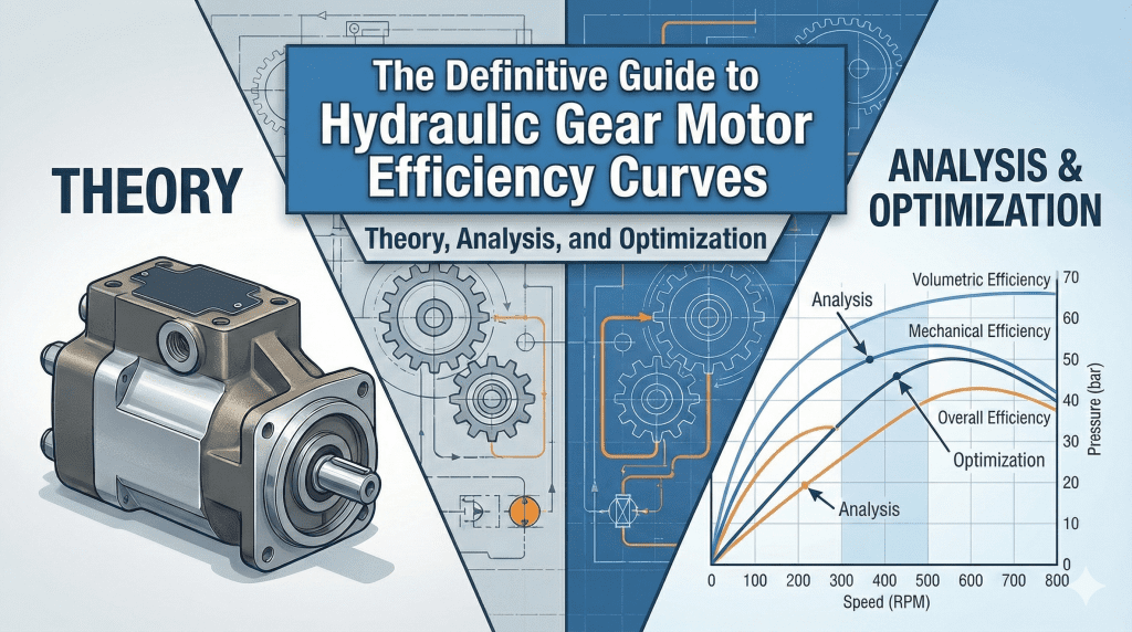
4.5 Efficiency Curves
Efficiency in gear pumps is a composite of Volumetric Efficiency ($\eta_v$) and Mechanical Efficiency ($\eta_m$).
-
Volumetric Efficiency: Internal gear pumps generally maintain higher volumetric efficiency at lower speeds and higher viscosities due to the longer sealing path of the crescent. External gear pumps suffer from greater slip at low viscosities unless run at high speeds.
-
Mechanical Efficiency: External gear pumps often have lower mechanical drag with thin fluids, but as viscosity increases, the drag on the peripheral flow path rises sharply, degrading mechanical efficiency.
5. Industry Applications: Strategic Deployment
Understanding where each pump excels helps in building a robust fluid handling system.
5.1 Hydraulic Power Units (Mobile & Industrial)
-
Preferred Technology: External Gear Pump.
-
Application Context: Excavators, tractors, log splitters, and industrial presses.
-
Reasoning: These applications require high pressure to generate force (F = P x A). The fluid is clean hydraulic oil (low viscosity). The pump must be small, light, and inexpensive. Noise is a secondary concern.
5.2 Chemical Processing (Polymers, Resins, Adhesives)
-
Preferred Technology: Internal Gear Pump.
-
Application Context: Transferring resins, dosing additives, unloading tankers of solvents.
-
Reasoning: The fluid viscosity can vary wildly. Polymers are often shear-sensitive; high shear from an external pump could break molecular chains, reducing the product’s quality. Internal pumps move the fluid gently and can be equipped with heating jackets to keep resins molten.
5.3 Food and Beverage (Chocolate, Fats, Syrups)
-
Preferred Technology: Internal Gear Pump.
-
Application Context: Pumping chocolate, peanut butter, corn syrup, and vegetable oils.
-
Reasoning: Chocolate is a non-Newtonian fluid that degrades if sheared or overheated. Internal gear pumps are available in hygienic stainless steel with sanitary fittings. They handle the suspended solids (sugar crystals) better than tight-tolerance external pumps. The low speed prevents heat buildup which could caramelize the product.
5.4 Fuel Handling (Diesel, Kerosene, Heavy Oil)
-
Preferred Technology: Mixed.
-
Thin Fuels (Diesel): External Gear Pumps are cost-effective for simple transfer.
-
Heavy Fuels (Bunker C, Asphalt): Internal Gear Pumps are mandatory due to the high viscosity and the need for strong suction lift to pull cold oil from storage tanks.
-
5.5 Precision Metering
-
Preferred Technology: External Gear Pump (Specialized).
-
Application Context: Dosing chemical additives, colors, or catalysts.
-
Reasoning: Precision-machined external gear pumps (often called “spin pumps” in fiber manufacturing) offer pulseless flow that is strictly linear with RPM. They can be manufactured for extremely low flow rates (e.g., 0.06 GPM) where internal gear pumps are too large.
6. Selection Guide: A Structured Approach for Procurement
Selecting the right gear pump is not merely about matching flow and pressure; it involves a holistic analysis of the fluid and the system.
Step 1: Analyze Fluid Properties
-
Viscosity:
-
If $\mu < 100$ cP: External Gear Pump is likely more cost-effective.
-
If $\mu > 500$ cP: Internal Gear Pump is strongly recommended to avoid cavitation and efficiency loss.
-
-
Abrasiveness:
-
Both pumps struggle with abrasives. However, Internal Gear Pumps are superior because the fluid velocity is lower, reducing erosive wear. Furthermore, the internal design has only one bearing exposed to the fluid, whereas the external design has four. Hardened materials (Tungsten Carbide, Ceramic) are mandatory for both.
-
-
Shear Sensitivity:
-
If the fluid is shear-sensitive (latex, emulsions), Internal Gear Pump is the only safe option.
-
Step 2: Define System Requirements
-
Pressure:
-
System Pressure > 300 PSI: External Gear Pump is required.
-
System Pressure < 200 PSI: Internal Gear Pump is preferred for efficiency and noise control.
-
-
Inlet Conditions (NPSH):
-
If the pump is located above the tank (suction lift) or the inlet line is long/restrictive, the Internal Gear Pump’s superior Net Positive Suction Head Required (NPSHr) makes it the safer choice to prevent cavitation.
-
Step 3: Select Materials of Construction
-
Housing:
-
Cast Iron: Standard for oil and non-corrosive fuels. Good dampening properties.
-
Stainless Steel (316): Required for corrosive chemicals and food applications. Note: Stainless steel has poor galling resistance, so internal clearances must be wider, reducing efficiency with thin fluids.
-
-
Bushings/Bearings:
-
Carbon Graphite: Good for low viscosity, provides some self-lubrication.
-
Bronze: Standard for oil service.
-
Tungsten Carbide: Mandatory for abrasive fluids (e.g., inks, paints).
-
Step 4: Drive and Sealing Options
-
Drive:
-
Direct Drive (Motor speed): Suitable for External Gear Pumps handling thin fluids.
-
Gear Reducer / V-Belt: Essential for Internal Gear Pumps handling viscous fluids to reduce speed (e.g., down to 500 RPM or lower).
-
-
Sealing:
-
Packing: Low cost, leaks slightly (required for cooling). Good for asphalt.
-
Lip Seal: Standard for low-pressure oil.
-
Mechanical Seal: Standard for industrial chemicals.
-
Magnetic Drive (Sealless): Eliminates shaft leakage entirely. Critical for hazardous/toxic fluids. Both pump types support this, but it adds significant cost.
-
7. Maintenance, Troubleshooting, and Failure Analysis
Even with perfect selection, pumps require maintenance. Understanding failure modes is critical for plant reliability.
7.1 Cavitation
-
Symptoms: The pump sounds like it is pumping gravel. Excessive vibration. Pitting damage on the gear teeth faces.
-
Mechanism: The pressure at the inlet drops below the fluid’s vapor pressure. Vapor bubbles form and then violently collapse when they reach the high-pressure discharge side.
-
Root Causes: Inlet filter clogged, fluid viscosity too high (cold fluid), pump running too fast, inlet line too small.
-
Correction: Clean filters, heat the fluid, slow the pump down, or switch to an Internal Gear Pump with larger inlet ports.
7.2 Aeration (Air Entrainment)
-
Symptoms: Pump is noisy (whining/grinding). Fluid looks foamy or milky.
-
Mechanism: Air is being drawn into the fluid stream. Unlike cavitation bubbles, air bubbles do not collapse violently but they compress, causing heat and erratic flow.
-
Root Causes: Loose fittings on the suction line, low tank level (vortexing), worn shaft seal allowing air ingress.
-
Correction: Tighten suction fittings, increase tank level, replace shaft seals.
7.3 Overheating
-
Symptoms: Paint bubbling on pump housing. Seized shaft. Smoke.
-
Mechanism: Friction heat is not being dissipated.
-
Root Causes: Running dry (no fluid), relief valve is bypassing internally for too long (100% recirculation), overtightened packing gland.
-
Correction: Install run-dry protection (power monitor), pipe relief valve back to the tank, loosen packing.
7.4 Internal Wear (Slippage)
-
Symptoms: Pump runs but flow rate has dropped significantly. Cannot build pressure.
-
Mechanism: Clearances between gears and housing have increased due to abrasion or erosion.
-
Root Causes: Abrasive fluid, normal wear over time, corrosion.
-
Correction:
-
Internal Pump: Adjust rotor end clearance. Replace bushings and idler pin.
-
External Pump: Replace wear plates or the entire pump unit.
-
8. Frequently Asked Questions (FAQ)
Q1: Which pump is cheaper, internal or external gear? A: Generally, External Gear Pumps are less expensive to purchase initially due to their simpler, symmetrical design and high-volume manufacturing for the mobile hydraulic market. Internal gear pumps are more complex to cast and machine, leading to a higher initial CAPEX, though their repairability can lead to lower long-term OPEX.
Q2: Can I use a gear pump for water? A: It is not recommended. Water has very low viscosity (1 cP) and poor lubricating properties. Gear pumps rely on the pumped fluid to lubricate internal bearings. Pumping water leads to rapid bearing wear and high slippage (low efficiency). If you must pump water with a gear pump, it requires special composite gears and bearings, but a centrifugal pump is almost always a better choice.
Q3: How do I reduce the noise of my hydraulic gear pump? A:
-
Check for cavitation or aeration (the most common causes of noise).
-
Switch to a Helical or Herringbone gear profile if possible.
-
Use flexible hoses instead of hard piping to isolate vibration.
-
Consider replacing an external gear pump with an Internal Gear Pump or a Screw Pump if the pressure requirements allow.
Q4: What is the “Crescent” in an internal gear pump? A: The crescent is a stationary, moon-shaped part of the pump head located between the inner and outer gears. It acts as a seal, separating the suction side from the discharge side. Without it, fluid would simply recirculate inside the pump rather than being forced out the discharge.
Q5: Can gear pumps run in reverse? A: Yes, most gear pumps are bi-rotational and can pump in either direction with equal efficiency. However, you must check the pressure relief valve. Standard internal relief valves are designed for one flow direction. If you reverse the pump without reversing the relief valve orientation, you lose over-pressure protection, which can be dangerous.
9. Conclusion
The divergence between Internal and External Gear Pumps represents a classic engineering trade-off between power and process.
-
The External Gear Pump is the master of Force. It is the compact, high-pressure muscle behind hydraulic machinery, prioritizing rigidity and cost-efficiency to perform work in tough environments.
-
The Internal Gear Pump is the master of Flow. It is the gentle giant of the process industry, prioritizing hydraulic efficiency, suction capability, and fluid integrity to transport the world’s most difficult liquids.
For the Carehyd customer, the choice is clear: define the fluid, determine the pressure, and select the architecture that aligns with the physics of the application. By adhering to the principles outlined in this guide, operators can ensure their fluid handling systems achieve the golden trifecta of reliability, efficiency, and safety.
2 comments
Hello would you mind letting me know which web host
you’re utilizing? I’ve loaded your blog in 3 completely different web browsers and I must
say this blog loads a lot faster then most.
Can you recommend a good web hosting provider at
a fair price? Kudos, I appreciate it!
i use ovh