

A hydraulic pressure reducing valve is an essential pressure control component used to maintain a lower, controlled pressure in a specific section of a hydraulic circuit. It allows different machine functions to operate at different pressure levels without requiring separate hydraulic power sources.
In industrial machinery, not every actuator requires the full pressure generated by the hydraulic pump. Clamping cylinders, positioning mechanisms, pilot control circuits, and auxiliary functions may need significantly lower operating pressures than the main hydraulic system.
A correctly selected pressure reducing valve helps control these secondary pressure levels, support consistent machine operation, and reduce the risk of excessive force being applied to sensitive components.
However, selecting the wrong valve can lead to unstable pressure, insufficient actuator force, excessive heat generation, or premature component wear.
This guide explains how hydraulic pressure reducing valves work, the differences between direct-acting and pilot-operated designs, their industrial applications, and the technical factors engineers should consider when selecting and troubleshooting these valves.
What Is a Hydraulic Pressure Reducing Valve?
A hydraulic pressure reducing valve is a normally open pressure control valve that regulates downstream pressure by restricting flow from a higher-pressure supply line.
Its primary purpose is to maintain a selected pressure level in a secondary hydraulic circuit while allowing the upstream system to operate at a higher pressure.
For example, a hydraulic power unit may supply oil at 180 bar, while a workpiece clamping circuit requires no more than approximately 60 bar.
Instead of reducing the pressure of the entire hydraulic system, a pressure reducing valve can be installed in the clamping branch to limit the pressure supplied to that function.
The valve automatically responds to pressure changes downstream by adjusting an internal spool or other control element.
Unlike a conventional pressure relief valve, which limits system pressure by discharging excess fluid, a pressure reducing valve primarily controls the pressure delivered to a specific branch.
The key distinction is that a pressure reducing valve senses and regulates downstream pressure, not the main supply pressure.
It is also important to understand that the valve cannot increase pressure above the available supply pressure. Nor does the outlet necessarily remain at the set pressure when the connected actuator requires less pressure.
How Does a Hydraulic Pressure Reducing Valve Work?
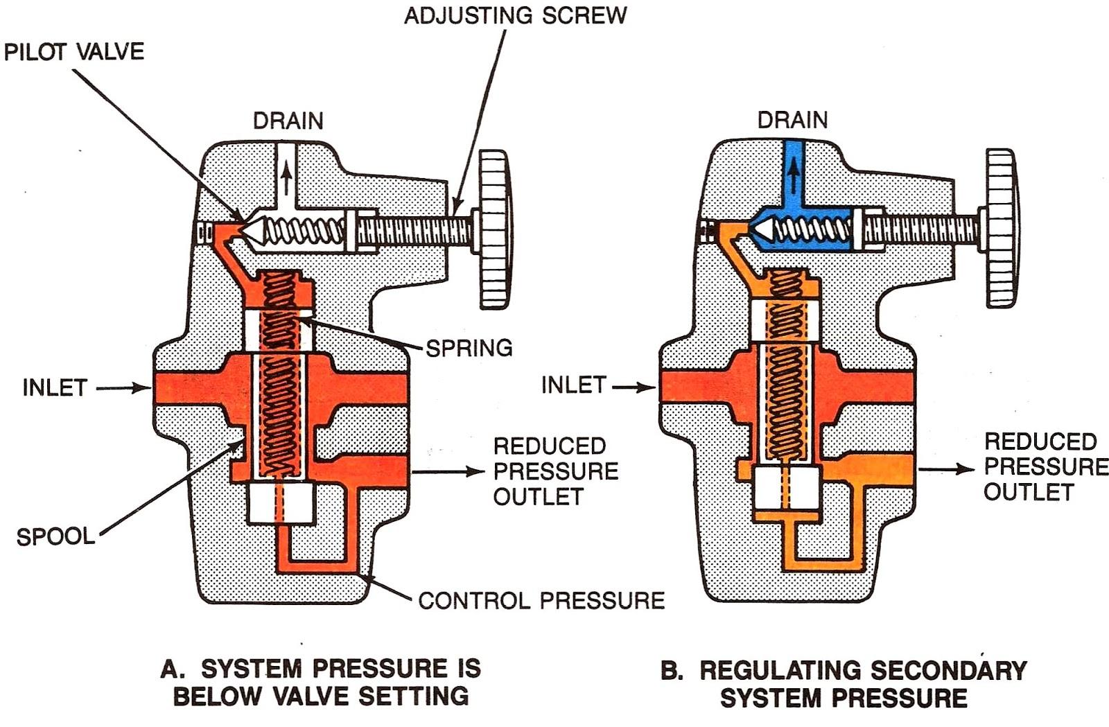
The working principle of a hydraulic pressure reducing valve is based on the balance between spring force and hydraulic pressure acting on an internal control element.
In a conventional hydraulic reducing valve, the spring initially holds the valve in an open position. As downstream pressure increases, hydraulic force acts against the spring and progressively restricts the flow passage.
The operating process can be divided into three stages.
1. Normal Operation: Valve Open
When downstream pressure is below the adjusted pressure setting, the valve remains open or substantially open.
Hydraulic oil flows from the inlet toward the secondary circuit with relatively little restriction.
During this stage, the pressure required by the connected actuator is determined primarily by its load and the hydraulic circuit conditions.
The valve does not automatically generate the full adjusted pressure when the load does not require it.
2. Pressure Regulation: Valve Throttling
As the downstream pressure approaches the preset value, the hydraulic force acting on the valve’s control element increases.
This force counteracts the adjustable spring and moves the spool toward a throttling position.
The resulting restriction creates a pressure difference between the inlet and outlet, allowing the secondary circuit to operate at a lower pressure than the main supply.
The valve continuously adjusts its opening as operating conditions change.
3. Pressure Recovery: Valve Reopening
When the downstream pressure decreases because the actuator requires additional oil or the hydraulic load changes, the spring moves the control element toward a more open position.
The valve allows additional flow into the secondary circuit.
This feedback mechanism enables the valve to regulate the pressure during changing operating conditions, within its rated flow and pressure limits.
Why Downstream Pressure Matters
Pressure reducing valves are often described as devices that maintain constant pressure. In practice, their ability to regulate pressure depends on the available inlet pressure, load demand, flow rate, and valve characteristics.
Three important principles apply:
- The inlet pressure must be sufficiently higher than the desired outlet pressure for the valve to regulate effectively.
- The actual outlet pressure may be below the setting when the actuator does not generate enough load pressure.
- The valve cannot independently control actuator speed; speed primarily depends on flow rate and actuator displacement.
Understanding these limitations is essential when designing hydraulic circuits and diagnosing pressure-related problems.
Main Types of Hydraulic Pressure Reducing Valves
Hydraulic pressure reducing valves are available in different constructions and operating configurations.
The most common distinction is between direct-acting pressure reducing valves and pilot-operated pressure reducing valves.
Other important distinctions include reducing-only versus reducing/relieving operation, as well as manually adjustable versus electronically controlled pressure settings.
1. Direct-Acting Pressure Reducing Valve
A direct-acting pressure reducing valve uses a spring and pressure-sensitive spool or control element to regulate downstream pressure without a separate hydraulic pilot stage.
When the secondary pressure reaches the adjusted setting, the control element moves directly against the spring force and restricts the inlet flow.
Main advantages:
- Relatively simple mechanical construction
- Compact design suitable for limited installation space
- Fast response in many low-flow applications
- Straightforward adjustment and maintenance
- Often economical for localized pressure control
Typical applications:
Direct-acting reducing valves are commonly considered for compact hydraulic circuits, pilot controls, brake-release functions, and relatively low-flow auxiliary systems.
Their principal limitation is that pressure regulation can become less stable or less accurate as flow demand increases, depending on the valve design.
2. Pilot-Operated Pressure Reducing Valve
A pilot-operated pressure reducing valve uses a smaller pilot stage to control the movement of a larger main-stage spool.
The pilot stage senses the regulated pressure and controls hydraulic pressure within the main valve.
When the downstream pressure reaches the setting, the pilot mechanism creates the pressure conditions necessary to move the main spool and restrict inlet flow.
This construction allows the valve to regulate larger flows without relying entirely on a large direct mechanical spring force.
Main advantages:
- Suitable for higher flow requirements
- Stable regulation across a broader range of operating conditions
- Appropriate for larger hydraulic systems
- Available with a variety of pressure adjustment ranges
- Well suited to industrial equipment with changing hydraulic demands
Typical applications:
Pilot-operated designs are frequently used in hydraulic power units, industrial presses, material handling equipment, and multi-actuator hydraulic circuits.
However, they usually have more complex internal passages and may respond differently to rapid pressure changes than direct-acting designs.
Direct-Acting vs. Pilot-Operated Pressure Reducing Valves
| Feature | Direct-Acting Valve | Pilot-Operated Valve |
|---|---|---|
| Operating principle | Spring and main control element act directly | Pilot stage controls the main spool |
| Construction | Relatively simple | More complex |
| Typical flow applications | Low to medium | Medium to high |
| Response | Often faster | Generally smoother for larger flows |
| Pressure stability | Depends on flow and operating conditions | Often better across varying flow rates |
| Cost | Usually lower | Usually higher |
| Common applications | Compact circuits and auxiliary controls | Larger industrial hydraulic systems |
These are general design characteristics rather than fixed performance limits. Actual flow capacity, response time, and pressure accuracy should always be confirmed using the manufacturer’s technical data.
3. Pressure Reducing vs. Pressure Reducing/Relieving Valves
Another important distinction is whether the valve includes a secondary-pressure relief function.
Reducing-only valves primarily restrict incoming flow when the downstream pressure reaches the preset level.
A non-relieving valve cannot necessarily release pressure that develops downstream because of an external mechanical load, thermal expansion, or trapped hydraulic fluid.
Reducing/relieving valves can regulate inlet flow and provide a controlled path for excess downstream pressure to discharge into the tank line.
For example, a hydraulic clamping cylinder may experience additional force from a machine mechanism after the reducing valve has already restricted incoming flow.
A relieving-type pressure reducing valve can help limit the resulting increase in secondary pressure, provided its relief capacity is suitable for the application.
The relieving function does not automatically make the valve a replacement for the hydraulic system’s main overpressure protection.
4. Proportional Pressure Reducing Valves
Traditional hydraulic reducing valves are commonly adjusted manually using a screw or knob.
Proportional pressure reducing valves use an electrical input to vary the regulated pressure.
Their pressure setting can be adjusted through an appropriate electronic control system, making them useful in automated equipment requiring multiple pressure stages.
Applications include:
- Automated clamping systems
- Injection molding machinery
- Industrial testing equipment
- Variable-pressure manufacturing processes
- Electrically controlled hydraulic manifolds
For an example of this technology, see the Rexroth ZDRE proportional pressure reducing valve listed by Carehyd.
The exact electrical requirements, pressure range, hydraulic port configuration, and control performance depend on the selected model.
Hydraulic Pressure Reducing Valve vs. Pressure Relief Valve
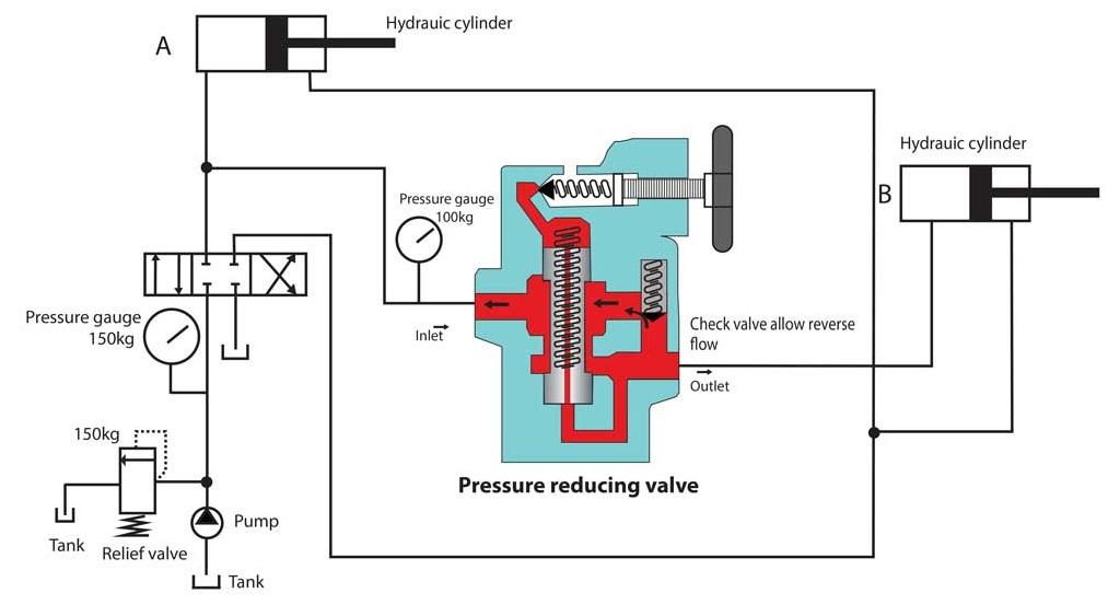
A hydraulic pressure reducing valve and a hydraulic pressure relief valve are both pressure control devices, but they perform different functions.
Confusing them can result in improper circuit operation and insufficient pressure protection.
| Comparison | Pressure Reducing Valve | Pressure Relief Valve |
|---|---|---|
| Primary function | Controls secondary or downstream pressure | Limits excessive pressure in the protected circuit |
| Pressure sensed | Downstream pressure | Pressure at the protected line |
| Normal position | Normally open | Normally closed |
| Main operating action | Restricts inlet flow | Opens a discharge path when required |
| Installation | Usually in a lower-pressure branch | Commonly connected to the main pressure line |
| Typical purpose | Actuator pressure regulation | System overpressure protection |
| Common application | Hydraulic clamping circuit | Pump and system pressure limitation |
Example: A Hydraulic System Requiring Both Valves
Consider an industrial machine with a main hydraulic system and a lower-pressure clamping mechanism.
The main hydraulic supply may operate at a higher pressure to support the machine’s primary actuator.
A pressure reducing valve controls the pressure delivered to the clamping circuit.
Meanwhile, a pressure relief valve limits excessive pressure in the main supply system.
These two valves work together because they address different pressure-control requirements.
For a related product example, Carehyd also lists the DBD Series direct-operated pressure relief valve.
A relief valve should not be substituted for a reducing valve merely because both components have adjustable pressure settings.
What About Hydraulic Sequence Valves?
Sequence valves are another category of hydraulic pressure control valves.
While a reducing valve regulates downstream pressure, a sequence valve opens a flow path when a specified pressure condition is reached.
Sequence valves are often used to coordinate the order of hydraulic operations.
For example, a machine might need to complete a clamping operation before allowing a second hydraulic function to begin.
The two valve types therefore serve different control purposes and are not automatically interchangeable.
Industrial Applications of Hydraulic Pressure Reducing Valves
Pressure reducing valves are particularly valuable in machines that require multiple hydraulic functions operating at different pressure levels.
Hydraulic Clamping Systems
In machine tools and automated manufacturing equipment, excessive clamping force can damage workpieces or fixtures.
A pressure reducing valve can limit the hydraulic pressure supplied to the clamping cylinders.
This allows the clamping function to use a lower pressure than the machine’s main hydraulic supply.
Hydraulic Presses
Industrial presses may contain separate circuits for pressing, positioning, auxiliary movement, and tooling functions.
A hydraulic pressure reducing valve can establish an appropriate maximum pressure for a lower-pressure auxiliary branch while the main press circuit retains its higher operating pressure.
Injection Molding Machinery
Injection molding systems may require different hydraulic pressure levels for specific machine functions.
Reducing valves can help regulate selected auxiliary circuits, while proportional pressure control valves allow pressure settings to be varied according to machine operating requirements.
Construction and Agricultural Equipment
Mobile hydraulic equipment often contains auxiliary functions with pressure requirements below those of the main working circuit.
Suitable pressure reducing valves can help control these functions without lowering the supply pressure available to other machine operations.
Industrial Hydraulic Power Units
A centralized hydraulic power unit may supply several machines or actuators.
Pressure reducing valves allow individual branches to be configured for different pressure requirements, subject to the power unit’s available pressure and flow capacity.
Hydraulic Test Benches
Hydraulic testing equipment may require adjustable and repeatable pressure limits to evaluate components under different operating conditions.
Suitable reducing valves, including proportional versions, can form part of these pressure regulation systems.
How to Select the Right Hydraulic Pressure Reducing Valve
Choosing the correct hydraulic pressure reducing valve requires an evaluation of the complete operating conditions, not simply the maximum pressure rating.
The following factors are particularly important.
1. Required Downstream Pressure
Determine the pressure required by the secondary circuit.
The valve’s adjustment range should include this pressure with sufficient control resolution for the intended application.
A valve with a very broad adjustment range is not necessarily the best choice for precise low-pressure control.
2. Maximum Inlet Pressure
Identify the normal and maximum supply pressures.
The selected valve must withstand the maximum pressure expected at its inlet, including pressure transients considered in the system design.
Do not confuse the maximum allowable inlet pressure with the adjustable secondary-pressure range.
3. Flow Rate Requirements
Determine the minimum, normal, and maximum flow rates through the valve.
An undersized valve may create excessive pressure drop and prevent the secondary circuit from receiving enough flow.
An oversized valve may also provide less suitable regulation characteristics in some low-flow applications.
The manufacturer’s pressure-flow performance curves are more informative than a nominal port size alone.
4. Available Pressure Differential
A hydraulic reducing valve requires adequate pressure difference between its inlet and controlled outlet.
For example, if the inlet pressure falls below the desired outlet pressure, the valve cannot maintain the selected setting.
Even when the inlet is nominally above the setting, insufficient pressure differential at maximum flow can result in pressure regulation problems.
5. Reducing-Only or Reducing/Relieving Function
Evaluate whether external loads can raise the downstream pressure after the valve restricts inlet flow.
If the secondary circuit can experience load-induced pressure increases, a relieving-type valve or another appropriate pressure-protection arrangement may be necessary.
The valve’s relieving flow capacity must also be evaluated.
6. Drain and Tank-Line Requirements
Many hydraulic pressure reducing valves require a drain or tank connection to allow internal leakage or pilot flow to return to the reservoir.
Some designs incorporate this connection into a three-way reducing/relieving function.
Excessive drain-line backpressure can interfere with pressure regulation and may change the effective pressure setting.
Always confirm the required connection arrangement and allowable drain pressure from the exact valve datasheet.
7. Hydraulic Fluid and Contamination Control
The hydraulic fluid must be compatible with the valve’s internal materials and seals.
Viscosity, operating temperature, and contamination level can influence performance and service life.
Pilot-operated and precision-control valves may be particularly sensitive to contamination in their internal control passages.
Use filtration and fluid cleanliness levels appropriate to the manufacturer’s requirements.
8. Mounting and Control Requirements
Hydraulic pressure reducing valves are available in different installation formats, including:
- Threaded cartridge valves
- Sandwich plate valves
- Subplate-mounted valves
- Inline valves
- Manifold-integrated valves
Determine the required installation format, hydraulic interface, available space, and whether manual or electronic pressure adjustment is necessary.
Hydraulic Pressure Reducing Valve Selection Checklist
| Parameter | Information to Confirm |
|---|---|
| Inlet pressure | Normal and maximum pressure |
| Outlet pressure | Required setting and allowable variation |
| Flow rate | Minimum, normal, and maximum flow |
| Valve type | Direct-acting or pilot-operated |
| Secondary relief | Required or not required |
| Pressure differential | Available at operating flow |
| Fluid | Type, viscosity, temperature |
| Drain arrangement | Port configuration and allowable backpressure |
| Installation | Cartridge, inline, sandwich, or subplate |
| Control | Manual or proportional electronic control |
Before selecting a replacement valve, confirm the complete manufacturer model code and compare the original technical specifications.
Engineering Example: Pressure Reduction in a Hydraulic Clamping Circuit
Consider a manufacturing machine that uses one hydraulic power unit for both a main operating cylinder and a smaller clamping cylinder.
The main system operates at a higher pressure, but the clamping cylinder must be limited to a lower pressure to avoid excessive force on the workpiece.
The following values are illustrative, not actual measurements from a specific valve.
| Design Parameter | Example Value |
|---|---|
| Main hydraulic supply pressure | 180 bar |
| Desired clamping pressure | 60 bar |
| Maximum branch flow | 10 L/min |
| Clamping piston area | 25 cm² |
| Valve function | Pressure reducing, with relieving if required |
Step 1: Establish the Secondary Pressure
The pressure reducing valve is adjusted to approximately 60 bar.
When the clamping load generates sufficient pressure, the valve restricts flow to regulate the secondary circuit near the chosen setting.
Step 2: Estimate the Clamping Force
Hydraulic cylinder force can be estimated using:
Force = Pressure × Effective Piston Area
For convenient engineering units:
Force (kN) = Pressure (bar) × Area (cm²) × 0.01
Using the example values:
Force = 60 × 25 × 0.01 = 15 kN
The theoretical clamping force is approximately 15 kN, before accounting for friction, return-side pressure, and other mechanical effects.
Actual operating force should be confirmed through the complete cylinder and mechanism design.
Step 3: Evaluate Pressure Loss and Heat Generation
Pressure reduction across a throttling valve dissipates hydraulic energy when oil flows through the valve.
The approximate power dissipated across the pressure difference can be calculated as:
Power Loss (kW) ≈ Pressure Drop (bar) × Flow Rate (L/min) ÷ 600
Assuming a 120 bar pressure difference at 10 L/min:
Power Loss = 120 × 10 ÷ 600 = 2 kW
This indicates approximately 2 kW of hydraulic power dissipation while those pressure and flow conditions are maintained.
It does not mean that 2 kW of heat is continuously generated when the clamping circuit is stationary with negligible flow.
For continuously operating pressure-reduction circuits, thermal performance and overall energy efficiency should be evaluated carefully.
Step 4: Verify Valve Suitability
The chosen valve must support the inlet pressure, required secondary pressure, maximum branch flow, and hydraulic fluid conditions.
The engineer must also confirm whether the clamping circuit requires a relieving function to handle pressure generated by external forces.
This example shows why pressure settings alone are insufficient for choosing a suitable valve.
Installation and Adjustment Best Practices
Correct installation is essential for predictable hydraulic pressure control.
Verify the Hydraulic Port Connections
Identify the inlet, regulated outlet, and drain or tank connections using the manufacturer’s hydraulic symbol and technical documentation.
Port numbering is not universal across manufacturers.
Incorrect connections can prevent proper regulation or expose components to excessive pressure.
Install Pressure Measurement Points
Provide suitable pressure measurement points upstream and downstream of the reducing valve.
This allows maintenance personnel to verify the actual pressure differential and diagnose problems during operation.
Maintain Proper Drain Conditions
Where required, connect the valve’s drain port to an appropriate low-pressure return path.
Do not block a required drain port.
Check the maximum allowable return-line pressure before commissioning.
Adjust According to the Manufacturer’s Procedure
Follow the specific manufacturer’s instructions for initial adjustment and testing.
Verify the pressure setting under the relevant operating conditions rather than relying solely on a no-flow gauge reading.
Test the Complete Operating Cycle
Test the valve during normal operation, changing flow demand, and expected load variations.
Where applicable, verify the behavior of the downstream circuit during externally induced pressure increases.
All installation and adjustment work should follow appropriate hydraulic isolation, pressure-release, and machine safety procedures.
Common Hydraulic Pressure Reducing Valve Problems and Troubleshooting
Hydraulic pressure reducing valves can experience regulation problems because of contamination, incorrect installation, pressure losses, or component wear.
The following table summarizes common symptoms and possible causes.
| Problem | Possible Causes | Recommended Checks |
|---|---|---|
| Downstream pressure too high | Incorrect setting, blocked drain, sticking spool, external load pressure | Check setting, drain, valve operation, and relief requirement |
| Downstream pressure too low | Insufficient inlet pressure, excessive flow demand, clogged passages, internal leakage | Measure supply pressure and compare flow with performance curves |
| Pressure fluctuates | Air in system, unstable supply, contamination, control instability | Check oil condition, pressure signals, and hydraulic circuit |
| Valve produces unusual noise | Flow restriction, cavitation, unstable regulation, contamination | Check flow, inlet pressure, and operating conditions |
| Excessive oil temperature | Large continuous pressure drop, excessive throttling, system inefficiency | Evaluate pressure differential, flow, and heat dissipation |
| Slow actuator movement | Excessive restriction, insufficient available flow, blocked passages | Measure flow and compare inlet and outlet pressures |
How to Diagnose Pressure Creep
Pressure creep occurs when downstream pressure gradually increases above the expected regulated level.
Possible causes include internal leakage, contamination preventing the spool from closing correctly, drain-line problems, or pressure being introduced from another part of the circuit.
A non-relieving reducing valve may also be unable to discharge pressure created by a trapped or externally loaded downstream volume.
Pressure creep should therefore be investigated as a system-level problem rather than automatically treated as a faulty adjustment spring.
Why Does Downstream Pressure Drop Under Load?
If downstream pressure falls significantly below the valve setting during operation, possible explanations include insufficient supply pressure, excessive flow demand, or pressure losses across the valve and connecting lines.
The pressure gauge should be checked during the relevant machine operating cycle, and the readings should be compared with the valve’s published pressure-flow characteristics.
Maintenance Tips for Reliable Pressure Control
Preventive maintenance helps maintain the performance of hydraulic pressure reducing valves.
Maintain Hydraulic Oil Cleanliness
Follow the recommended fluid cleanliness limits and filtration requirements.
Contaminated hydraulic oil can cause spool sticking, restricted pilot passages, and accelerated internal wear.
Monitor Pressure Performance
Compare measured inlet and downstream pressures with established operating values.
Unexpected pressure changes may indicate an adjustment problem, altered flow demand, or mechanical wear.
Inspect Hydraulic Connections
Check for external leakage, damaged seals, loose connections, and incorrect drain arrangements.
Avoid Unnecessary Adjustments
Repeated adjustments without identifying the cause of pressure instability can make troubleshooting more difficult.
Use Manufacturer-Approved Replacement Components
When servicing a valve, use compatible seals and parts that match its exact model and revision.
For critical machinery, follow the manufacturer-specified inspection and maintenance procedures.
Frequently Asked Questions About Hydraulic Pressure Reducing Valves
What does a hydraulic pressure reducing valve do?
A hydraulic pressure reducing valve limits and regulates pressure in a secondary hydraulic circuit by restricting flow from a higher-pressure supply. It allows different parts of a hydraulic system to operate at different pressure levels.
Is a hydraulic pressure reducing valve normally open or normally closed?
Most conventional hydraulic pressure reducing valves are normally open. They allow flow into the secondary circuit until downstream pressure approaches the adjusted setting, at which point they begin restricting flow.
What is the difference between a pressure reducing valve and a relief valve?
A pressure reducing valve controls downstream pressure, while a conventional relief valve limits excessive pressure in the protected hydraulic circuit by opening a discharge path. Both may be required in the same system.
Which is better: a direct-acting or pilot-operated pressure reducing valve?
A direct-acting valve is often suitable for compact, lower-flow circuits where simplicity and response are important. A pilot-operated valve is commonly preferred for larger flows or applications requiring stable regulation across varying operating conditions. The correct choice depends on the manufacturer’s performance data.
Can a pressure reducing valve increase hydraulic pressure?
No. A conventional pressure reducing valve cannot raise downstream pressure above the available inlet pressure. It only limits or regulates pressure supplied from a higher-pressure source.
Can a hydraulic pressure reducing valve control cylinder speed?
Not directly. A pressure reducing valve primarily controls pressure. Hydraulic cylinder speed depends mainly on fluid flow rate and the cylinder’s effective area. Pressure regulation may influence movement under certain load conditions, but it is not a substitute for a properly designed flow-control system.
Do all pressure reducing valves have a relief function?
No. Some designs provide pressure reduction only, while others incorporate a secondary-pressure relief function. A reducing/relieving valve can discharge excess downstream pressure through an appropriate tank connection, within its rated capacity.
Why does a hydraulic pressure reducing valve need a drain line?
Some valve designs use a drain connection to return internal leakage or pilot oil to the reservoir. Correct drain pressure is important because excessive backpressure can affect regulation. The required arrangement depends on the valve model.
How do I select a replacement hydraulic pressure reducing valve?
Start by identifying the original manufacturer’s model number. Confirm the inlet pressure rating, secondary pressure range, flow capacity, valve function, mounting interface, fluid compatibility, and drain requirements before selecting a replacement.
Conclusion
A hydraulic pressure reducing valve plays an important role in controlling pressure within secondary hydraulic circuits.
By allowing selected machine functions to operate at lower pressure than the main hydraulic supply, these valves support appropriate actuator force, predictable pressure regulation, and reliable industrial equipment operation.
Understanding the differences between direct-acting, pilot-operated, reducing-only, and reducing/relieving designs is essential for selecting the correct valve.
Engineers should evaluate the complete hydraulic circuit, including inlet pressure, flow demand, available pressure differential, fluid characteristics, drainage requirements, and potential external loads.
A properly selected valve can provide reliable pressure regulation, but it must be matched to the actual machine requirements and verified against manufacturer specifications.
Need Help Choosing a Hydraulic Pressure Reducing Valve?
Selecting the correct valve is especially important when replacing an existing hydraulic component or designing a circuit with multiple pressure levels.
At Carehyd, we can help you review hydraulic valve options and identify suitable product models based on your technical requirements.
Explore our hydraulic valve products or contact Carehyd to discuss your application.
For a more accurate inquiry, please provide the valve model number, required inlet and outlet pressures, flow rate, mounting configuration, and hydraulic fluid type.
Contact Carehyd for hydraulic valve selection assistance and product availability.
